|
Chi-Tech
|
|
Chi-Tech
|
This tutorial demonstrates creating a structured mesh using gmsh: https://gmsh.info/
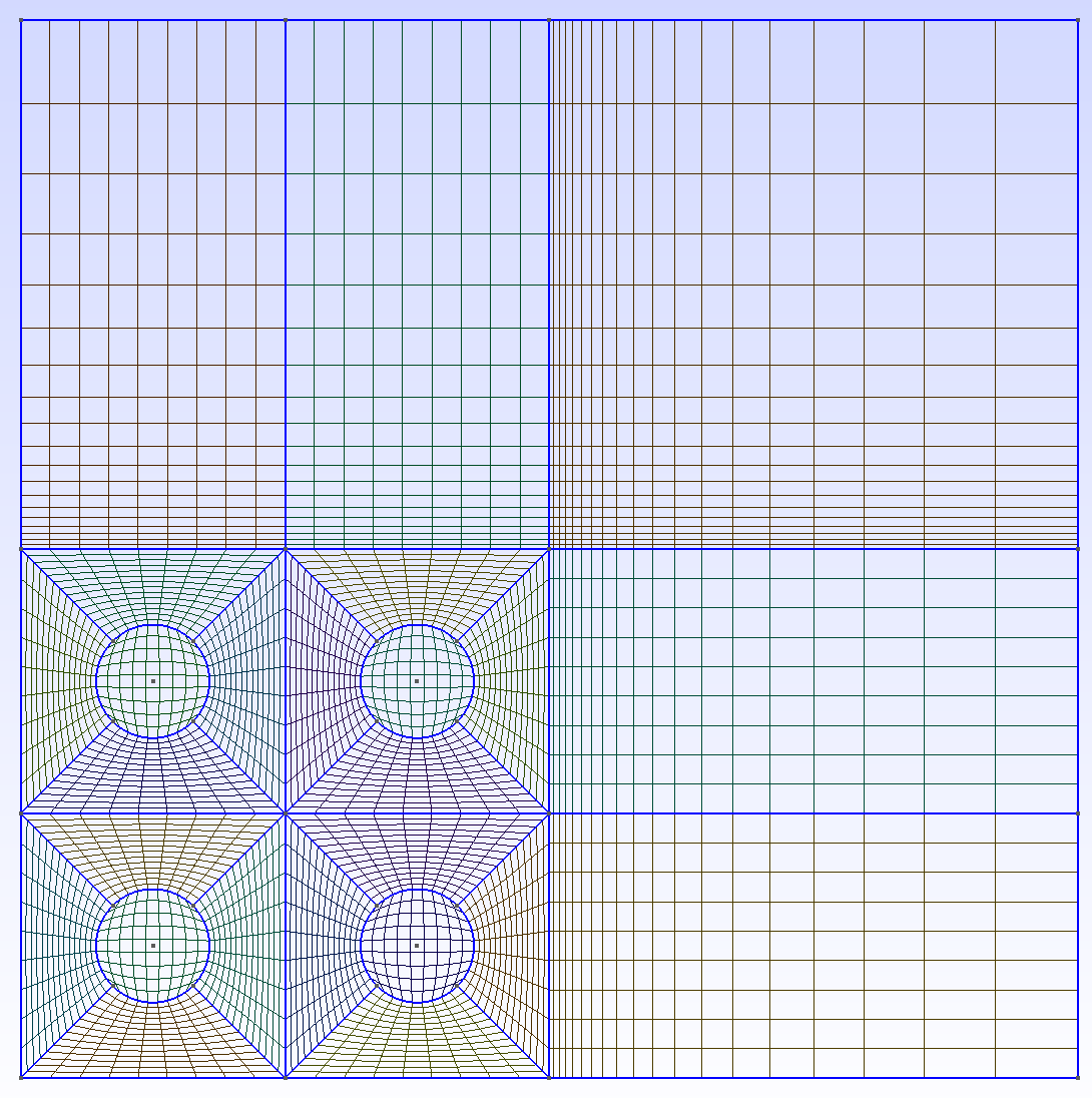
The geometry to be created and meshed with a structured mesh is shown below. The tutorial will describe how to build the geometry in steps.
Gmsh can be used soley from the terminal or it can be used through the gmsh graphical user interface (GUI). In this tutorial, the mesh will be created by entering text into a file and then having the GUI read the file and display the mesh. Instead of manually adding text to the input file, the GUI can also be used to create the mesh, although that is not done here. First, create a new file and open it with the gui so that text can be entered. The sample file in this tutorial will be called structured_ex.geo Note that the kernel option "Built-in" is used for this tutorial. If a different kernel is used, the general idea of this tutorial will still apply, but some details may be different. Additionally, gmsh version 4.0.6 is being used. Other versions of gmsh should also be usable with this tutorial, but some details may not apply.
The first step in creating a mesh is to create some shape that will be meshed. The shape to be meshed will be created by specifying points and then connecting these points with lines. For this tutorial, a square shape is first created. To create the square, four points are speficied and these are connected by four lines. The gmsh input is shown below and this is the first text to put into the structured_ex.geo file. Notice the points are specified with the syntax Point(i)={x,y,z} where "i" is the tag that identifies that point and "{x,y,z}". The tag identifying each point must be unique and tags must not be 0. For simplicity, sequentially increasing integers are used as tags in this tutorial. There is a fourth optional argument that can be used when building a point "Point(i)={x,y,z,d}" where "d" specifies how fine the mesh should be at that point. A lower number will result in a finer mesh. This optional argument is not used in this tutorial. In the input file, you can also define variables and use some common functions defined in gmsh. This is demonstrated below where variables pitch, circle_r, and bottom_left_cirle are deinfed and will be used later. In later input, the function Cos(x) is used.
pitch = 0.0126;
circle_r = 0.0108/2;
bottom_left_circle = pitch/2;

Point(1) = {0, 0, 0};
Point(2) = {pitch, 0, 0};
Point(3) = {pitch, pitch, 0};
Point(4) = {0, pitch, 0};
//
// Outer Box domain
//
Line(1) = {1, 2};
Line(2) = {2, 3};
Line(3) = {3, 4};
Line(4) = {4, 1};
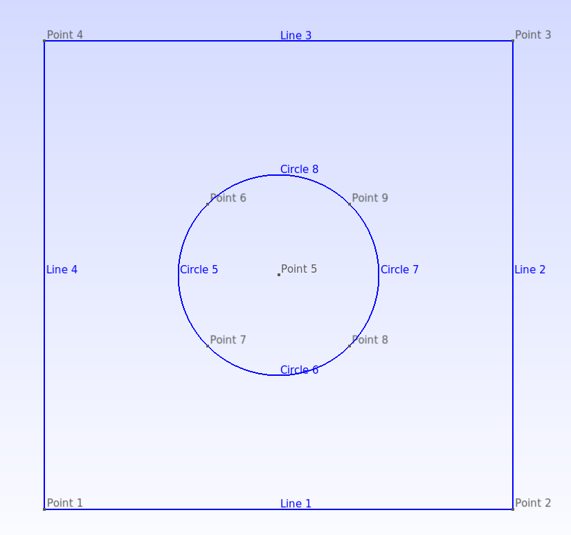
At this point, gmsh does not know that the four lines defined form a closed surface. In fact, we will not use the square directly, but instead break it into multiple several shapes. Next, a circle is created in the middle of the existing square. The variables defined previously as well as the Cos function is used in the example below. Point(5) is the center of the circle. The next 4 points are evenly spaced along the perimeter of the circle. The reason for the points being placed at locations that intersect the diagonals of the bounding square will be apparent in the next step.
Note the new syntax "Line Loop(1) = {-5,-6,-7,-8};" and "Surface(1) = {1};" which specifies to gmsh that the four lines 5,6,7,8 are meant to be connected into a loop and that this loop, given tag 1, defines a surface, also given the tag 1. The tag does not need to be the same, but in this case the surface and line loops are seperate entities and so can have the same tag. Note that when defining the line loops, some of the line tags start with negative numbers. The line loop must have a certain orientation. That is, the points which make up the lines and thus the line loop must be ordered. All loops are clockwise in this tutorial. You can mouse over the lines in the GUI to see the ording of the points. For example, Line Loop(1) consists of lines made up of points (6,7); (7,8); (8,9); (9,6). But this is backward with respect to clockwise orientation. The negative sign flips ordering of the points making up the line thus to be (6,7) becomes (7,6) etc.
// Points that make up the circle
Point(5) = {bottom_left_circle,bottom_left_circle,0.0};
Point(6) = {bottom_left_circle-circle_r*Cos(Pi/4.)/2.,bottom_left_circle+circle_r*Cos(Pi/4.)/2.,0.0};
Point(7) = {bottom_left_circle-circle_r*Cos(Pi/4.)/2.,bottom_left_circle-circle_r*Cos(Pi/4.)/2.,0.0};
Point(8) = {bottom_left_circle+circle_r*Cos(Pi/4.)/2.,bottom_left_circle-circle_r*Cos(Pi/4.)/2.,0.0};
Point(9) = {bottom_left_circle+circle_r*Cos(Pi/4.)/2.,bottom_left_circle+circle_r*Cos(Pi/4.)/2.,0.0};

// Curves that connect points defining circle
Circle(5) = {6,5,7};
Circle(6) = {7,5,8};
Circle(7) = {8,5,9};
Circle(8) = {9,5,6};
// specify closed loop to make surface
Curve Loop(1) = {-5,-8,-7,-6};
Surface(1) = {1};
To make a structured mesh in gmsh, shapes with four sides are needed. At this point, the circular shape can be meshed with a structured algorithm, but the region outside of the circle can't. This region is next broken into four sided shapes as shown in the input below.
// break area outside circle into four surfaces
// First define lines, the line loops, then the
// surfaces
Line(9) = {1,7};
Line(10) = {8,2};
Line(11) = {9,3};
Line(12) = {6,4};

Curve Loop(3) = {9,6,10,-1};
Curve Loop(4) = {-10,7,11,-2};
Curve Loop(5) = {-11,8,12,-3};
Curve Loop(6) = {-12,5,-9,-4};

Surface(2) = {3};
Surface(3) = {4};
Surface(4) = {5};
Surface(5) = {6};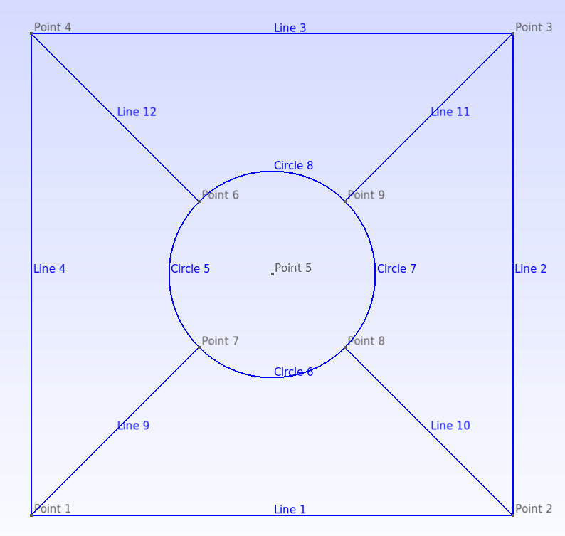
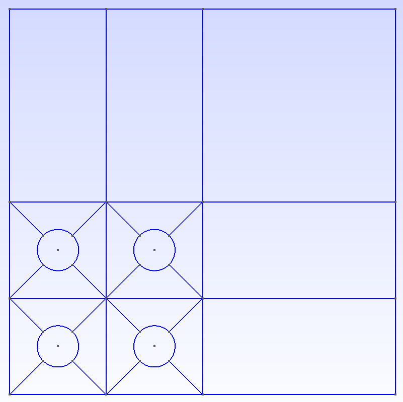
The single cell now created is copied four times and translated. The input for this is shown below. The variable "pitch" defined at the top of the file is used. Notice the "Coherence;" commant. This command removes repeated items such as repeated points and line. Some of the copied eneties overlap and without this command (test this out), several lines and points will overlap. The image below shows how to use the gui to see the new lines and points created by the duplication process. The tags for these new lines are needed for the next steps. It is possible that a different gmsh version may lead to different numbering, so the input in this tutorial may need to be adjusted.
Translate{ pitch, 0.0, 0.0} { Duplicata{Surface{1};}  }
Translate{ 0.0, pitch, 0.0} { Duplicata{Surface{1};}  }
Translate{ pitch, pitch, 0.0} { Duplicata{Surface{1};}  }

Translate{ pitch, 0.0, 0.0} { Duplicata{Surface{2};}  }
Translate{ 0.0, pitch, 0.0} { Duplicata{Surface{2};}  }
Translate{ pitch, pitch, 0.0} { Duplicata{Surface{2};}  }

Translate{ pitch, 0.0, 0.0} { Duplicata{Surface{3};}  }
Translate{ 0.0, pitch, 0.0} { Duplicata{Surface{3};}  }
Translate{ pitch, pitch, 0.0} { Duplicata{Surface{3};}  }

Translate{ pitch, 0.0, 0.0} { Duplicata{Surface{4};}  }
Translate{ 0.0, pitch, 0.0} { Duplicata{Surface{4};}  }
Translate{ pitch, pitch, 0.0} { Duplicata{Surface{4};}  }

Translate{ pitch, 0.0, 0.0} { Duplicata{Surface{5};}  }
Translate{ 0.0, pitch, 0.0} { Duplicata{Surface{5};}  }
Translate{ pitch, pitch, 0.0} { Duplicata{Surface{5};}  }

Coherence;
Next, the additional four sided shapes are created as shown in the first image at the top of the page. These five surfaces will be specified as being one physical surface in later input.
Point(104) = {0, 4*pitch, 0};
Point(105) = {pitch, 4*pitch, 0};
Point(106) = {2*pitch, 4*pitch, 0};
Point(107) = {4*pitch, 4*pitch, 0};

Point(108) = {4*pitch , 2*pitch, 0};
Point(109) = {4*pitch , pitch, 0};
Point(110) = {4*pitch , 0, 0};


Line(77) = {103,104};
Line(78) = {104,105};
Line(79) = {105,81};

Line(80) = {105,106};
Line(81) = {106,92};

Line(82) = {106,107};
Line(83) = {107,108};
Line(84) = {108,92};

Line(85) = {108,109};
Line(86) = {109,70};

Line(87) = {109,110};
Line(88) = {110,59};

Curve Loop(100) = {77,78,79,-65};
Curve Loop(101) = {81,-70,-79,80};
Curve Loop(102) = {82,83,84,-81};
Curve Loop(103) = {85,86,-56,-84};
Curve Loop(104) = {87,88,-46,-86};

Surface(100) = {100};
Surface(101) = {101};
Surface(102) = {102};
Surface(103) = {103};
Surface(104) = {104};
The surfaces created thus far are for construction purposes. We now specify the surfaces and lines that are physical. The physical lines are those defining a problem boundary. There are two types of surfaces in this mesh being created, those inside a cylinder and those outside a cylinder. Currently, the physical surface tags must start at 0 and increase sequentially to be used with chi-tech. The physical surface tag will serve as an array index for the stack of materials defined in a chi-tech input.
Physical Line(0) = {1,32,88};
Physical Line(1) = {87,85,83};
Physical Line(2) = {78,80,82};
Physical Line(3) = {4,76,77};
Physical Surface(0) = {1,13,18,23};
Physical Surface(1) = {2,3,4,5,28,42,57,71,37,52,66,77,33,47,61,72,100,101,102,103,104};
Next, a structured mesh will be defined. The "Transfinite Line" command is used. This command specifies opposing faces of the four sided shapes we will apply a structured mesh to and also how many grid points will be used when drawing mesh lines between the two defined faces. "Using Progression 1" indicates that the structured mesh should have uniform grading. Note that in the outer region of the geometry, "Using Progression 0.85" is used. This causes the meshing to be graded. Also note the input "Transfinite Line {-77, 79}" where the negative sign ensures that both lines have the same orientation which is required when using a grading. Test the input without this and see that the grading is flipped on one side.
After the transfinite lines are specified, each surface is specified to be mesh with a structured mesh by the syntax "Transfinite Surface {i}". Lastly, "Recombine Surface "*";" is included to specify that the mesh be made up of quadrilaterials. If this input is not included, then gmsh will create a mesh of structured triangles.
// bottom left cell
Transfinite Line {5, 7} = 10 Using Progression 1;
Transfinite Line {6, 8} = 10 Using Progression 1;
//
Transfinite Line {9, 10} = 15 Using Progression 1;
Transfinite Line {6, 1} = 10 Using Progression 1;
//
Transfinite Line {10, 11} = 15 Using Progression 1;
Transfinite Line {7, 2} = 10 Using Progression 1;
//
Transfinite Line {12, 11} = 15 Using Progression 1;
Transfinite Line {3, 8} = 10 Using Progression 1;
//
Transfinite Line {12, 9} = 15 Using Progression 1;
Transfinite Line {4, 5} = 10 Using Progression 1;
//
Transfinite Surface {1};
Transfinite Surface {2};
Transfinite Surface {3};
Transfinite Surface {4};
Transfinite Surface {5};


// bottom right cell
Transfinite Line {14, 16} = 10 Using Progression 1;
Transfinite Line {17, 15} = 10 Using Progression 1;
//
Transfinite Line {29, 31} = 15 Using Progression 1;
Transfinite Line {17, 32} = 10 Using Progression 1;
//
Transfinite Line {31, 45} = 15 Using Progression 1;
Transfinite Line {16, 46} = 10 Using Progression 1;
//
Transfinite Line {45, 60} = 15 Using Progression 1;
Transfinite Line {15, 41} = 10 Using Progression 1;
//
Transfinite Line {60, 29} = 15 Using Progression 1;
Transfinite Line {2, 14} = 10 Using Progression 1;
//
Transfinite Surface {28};
Transfinite Surface {42};
Transfinite Surface {57};
Transfinite Surface {71};
Transfinite Surface {13};

// top right cell
Transfinite Line {24, 26} = 10 Using Progression 1;
Transfinite Line {25, 27} = 10 Using Progression 1;
//
Transfinite Line {38, 40} = 15 Using Progression 1;
Transfinite Line {27, 41} = 10 Using Progression 1;
//
Transfinite Line {40, 55} = 15 Using Progression 1;
Transfinite Line {26, 56} = 10 Using Progression 1;
//
Transfinite Line {55, 69} = 15 Using Progression 1;
Transfinite Line {25, 70} = 10 Using Progression 1;
//
Transfinite Line {69, 38} = 15 Using Progression 1;
Transfinite Line {51, 24} = 10 Using Progression 1;
//
Transfinite Surface {37};
Transfinite Surface {52};
Transfinite Surface {66};
Transfinite Surface {77};
Transfinite Surface {23};

// top left cell
Transfinite Line {19, 21} = 10 Using Progression 1;
Transfinite Line {20, 22} = 10 Using Progression 1;
//
Transfinite Line {34, 36} = 15 Using Progression 1;
Transfinite Line {22, 3} = 10 Using Progression 1;
//
Transfinite Line {36, 50} = 15 Using Progression 1;
Transfinite Line {21, 51} = 10 Using Progression 1;
//
Transfinite Line {50, 64} = 15 Using Progression 1;
Transfinite Line {20, 65} = 10 Using Progression 1;
//
Transfinite Line {64, 34} = 15 Using Progression 1;
Transfinite Line {19, 76} = 10 Using Progression 1;
//
Transfinite Surface {33};
Transfinite Surface {47};
Transfinite Surface {61};
Transfinite Surface {72};
Transfinite Surface {18};


//outside region

Transfinite Line {65, 78} = 10 Using Progression 1;
Transfinite Line {-77, 79} = 20 Using Progression 0.85;
//
Transfinite Line {70, 80} = 10 Using Progression 1;
Transfinite Line {79, 81} = 20 Using Progression 0.85;
//
Transfinite Line {81, 83} = 20 Using Progression 0.85;
Transfinite Line {-82, 84} = 20 Using Progression 0.85;
//
Transfinite Line {84, 86} = 20 Using Progression 0.85;
Transfinite Line {56, 85} = 10 Using Progression 1;
//
Transfinite Line {86, 88} = 20 Using Progression 0.85;
Transfinite Line {46, 87} = 10 Using Progression 1;

Transfinite Surface {100};
Transfinite Surface {101};
Transfinite Surface {102};
Transfinite Surface {103};
Transfinite Surface {104};

Recombine Surface "*";
Note that currently only msh file format 2.2 in asci format is read by chi-tech.